


Classic Technologies Fuse Box Schematic:
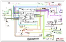 Click the schematic thumbnail to view PDF of the Classic Technologies schematic Fuse Box integrated into a vehicle.
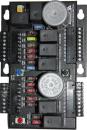
Classic Technologies Fuse Box Dimensions w/o cover:
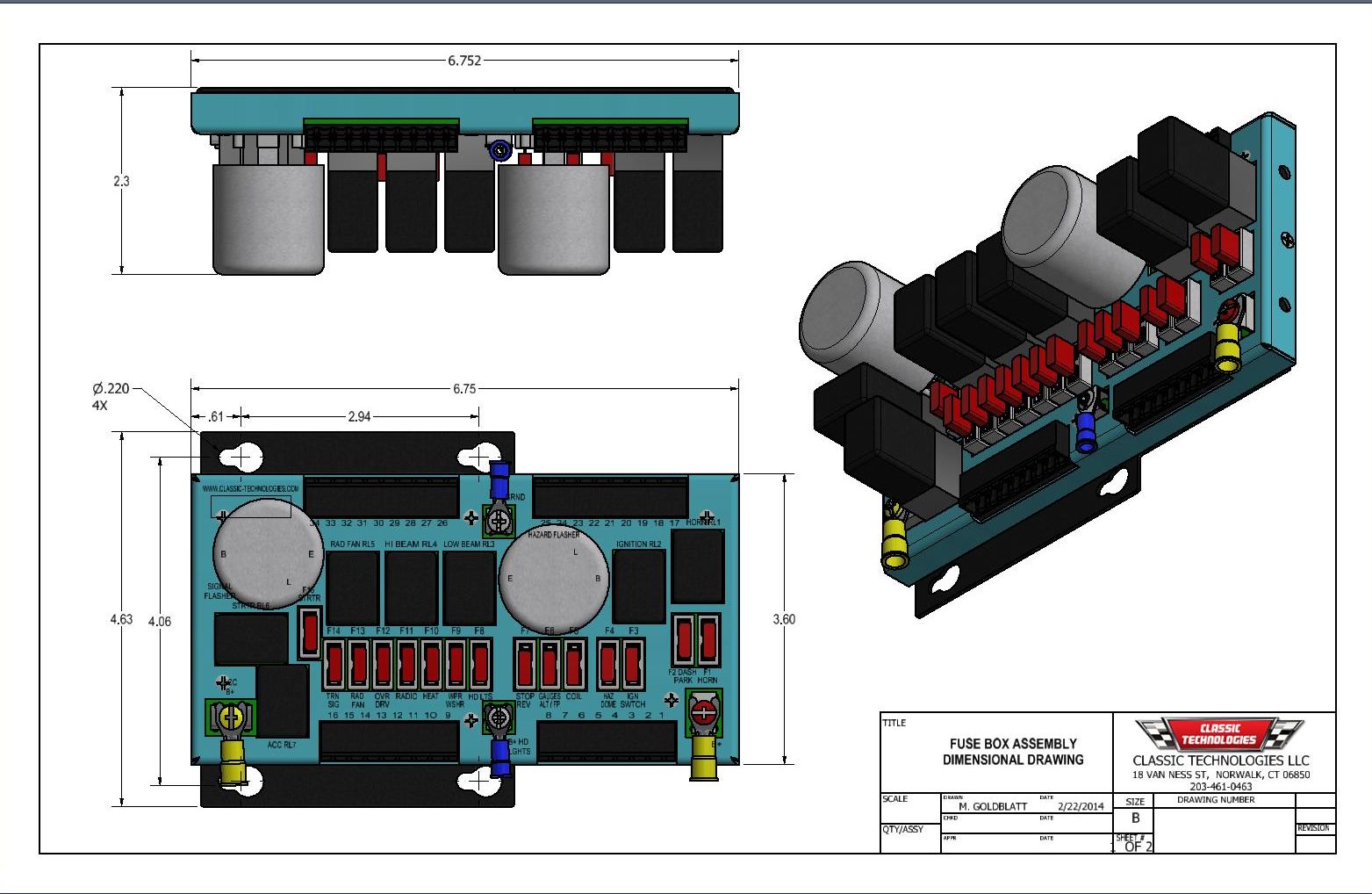
Click thumbnail
Classic Technologies Fuse Box Dimensions with cover:
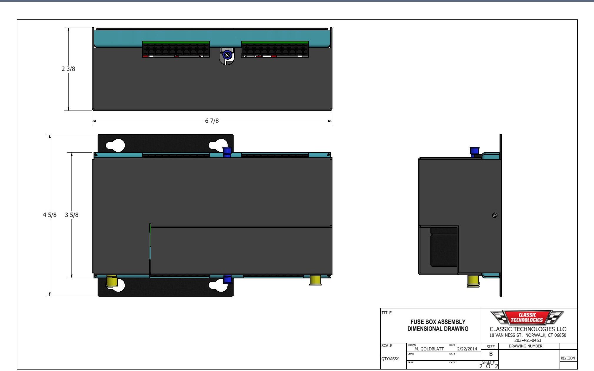
Click thumbnail
AMC Gremlin Barn Find and Restoration Story
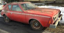 Click the Gremlin thumnail to read the story.
 Fuse Box
Click here to view specifications
Contact Us
For more information or questions on our products, click here.
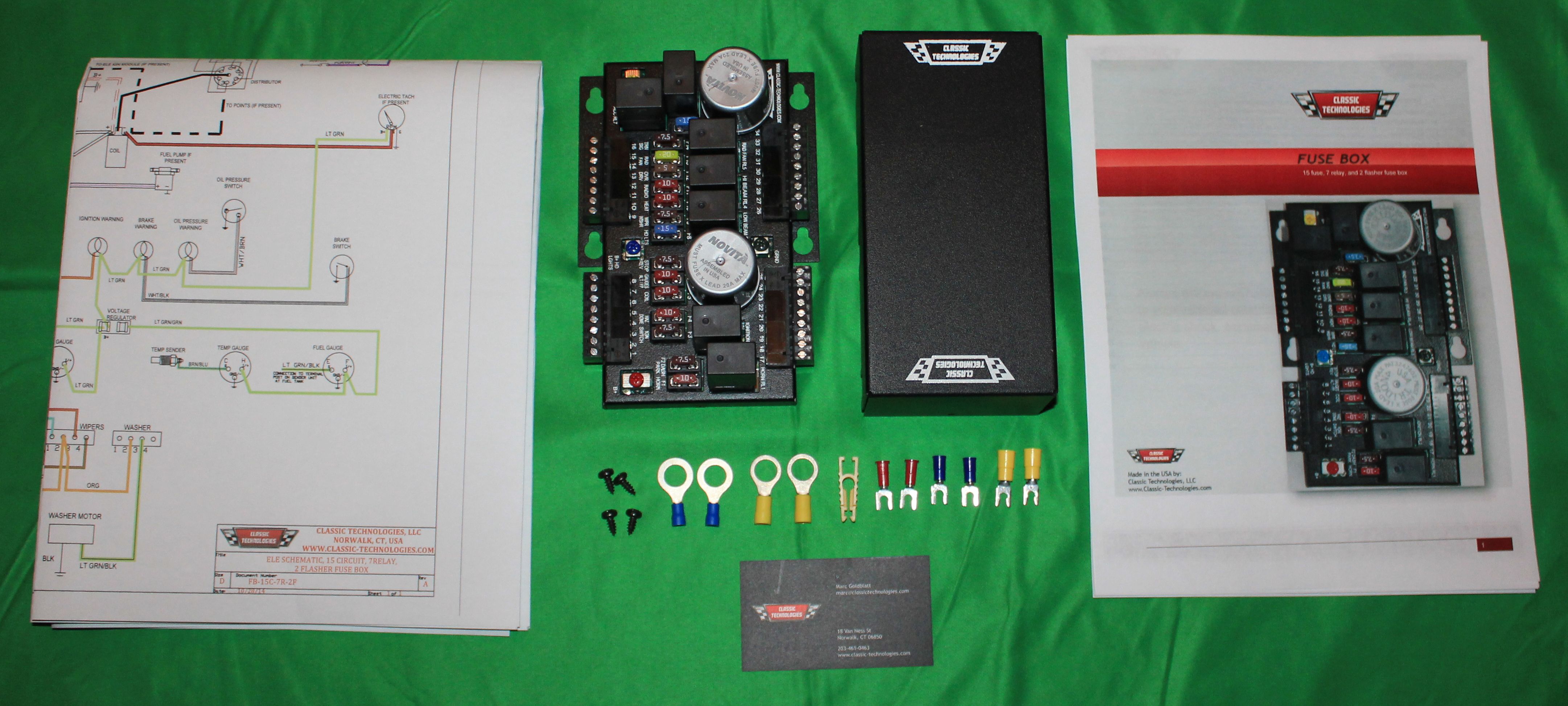
Classic Technologies proudly presents this aftermarket fuse box that is the perfect choice for rewiring your classic car, hot rod, or kit car. The 15 fuses, 7 relays, and 2 flashers coupled with the internal wiring takes the time, difficulty, and clutter out of rewiring a car properly. Its size was kept to a minimum to allow the most mounting flexibility. It is only 6 3/4" (171mm) long X 4 5/8" (81mm) wide X 2 3/16" (56mm) tall.
There is a short video to the left that highlights the main features of fuse boxes and provides some background information.
|
|
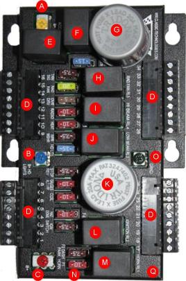
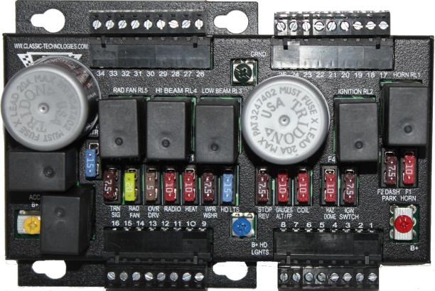
A. 12V power input Yellow screw terminal, spade lug connection. B. 12V power input to power the high and low beam headlight relays labeled I and J. Blue screw terminal spade lug connection. C. 12V power input. D. Four multi-position connectors that unplug to ease wire terminations. No special tooling needed; strip wire, insert and tighten screws to crimp wires. E. ACESSORY CIRCUIT RELAY: Activated when the ignition switch is in the RUN or ACCESSORY POSITION. This powers the fuses and relays on the accessory circuit.
Note: All fuses, relays, and flashers are in jacks for easy replacement. All relays are Micro ISO style, and are readily available at your local auto parts store or through Classic Technologies. F. Starter Relay G. Signal Flasher Long Life. (Lasts five times longer than thermal) Flasher can be replaced with a non load sensitive flasher for conversions to LED’s from incandescents. H. Radiator, Overdrive or Spare Relay I. High Beam Headlight Relay J. Low Beam Headlight Relay K. Hazard Flasher Long Life. (Lasts five times longer than thermal) Flasher can be replaced with a non load sensitive flasher for conversions to LED’s from incandescents. L. Ignition Relay. M. Horn Relay. N. 15 Fused Circuits broken into three groups. Constant Power: Ignition Power: Accessory Power. Fuses are ATM "mini". O. Fuse box ground (only ground for actuating relays).
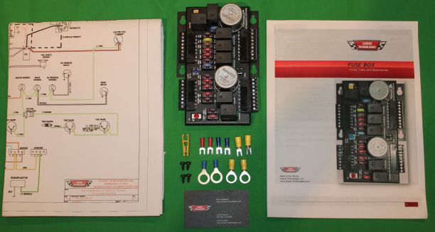
P. All circuitry on the printed circuit board (PCB) between the power inputs, fuses and relays makes the fuse box very compact and neat. It reduces the complexity of the harness and there is no chance of a miswire within the box. Q. Steel Black Powder Coated enclosure contoured to minimize size with easy mount keyhole slots on flanges. Other items included not shown in the picture: steel black powder coated cover, mounting screws, extra fuses, fuse puller, labels and fuse box legend. Color electrical schematic of fuse box wiring to car and installation manual. |